Solid State Chemistry – BSc Chemistry Notes
These are solid state chemistry notes for BSc chemistry students. Generally, solid state chemistry is teaches to graduation, BSc 1st year students. We also learn about solid state in class 12. Learn chemistry with these solid state notes.
Structure and bonding in solids
Now we learn about crystal structures and bonding's in solids
Crystal structure
The Solid state
- Solids form an important part of the world around us, providing materials with a definite shape and predictable properties.
- The shape of crystals varies from substance to substance.
- Any particular substance has crystals with a common shape.
- This common structure results from the regular arrangement of particles within the crystals and also reflects the degree of order within it, whether the particles are atoms, ion or molecules.
Structural Features of solids
- Crystalline solids have well defined shapes because their particles, for examples, atoms, molecules, or ions occur in an orderly arrangement.
- Amorphous solids have poorly defined shapes because their particles lack an orderly arrangement throughout the sample. For examples rubber and glass.
Figure 1 : Crystal _ Solid State Chemistry
The Crystal Lattice and the Unit Cell
- The particles in a crystal are packed tightly in an orderly, three-dimensional array.
- The arrangement of particles in a crystal is called the crystal lattice.
- The lattice consists of all points with identical surroundings; that is, there would be no variation in the structure if you moved from one lattice point to another.
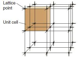
- Crystal lattices have a regular structure, made up of a number of repeating parts called unit cells (Figure 2).
Figure 2: Unit cell – Solid State Notes
- The unit cell is the smallest portion that gives the crystal if it is repeated in all directions.
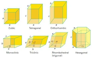
- There are seven crystal systems and fourteen types of unit cells that occur in nature (Figure 3).
Figure 3- Crystal Systems – Solid State Chemistry Notes
- The solid states of a majority of metallic elements, some covalent compounds, and many ionic compounds occur as cubic lattices.
- There are three types of cubic unit cells that occur in nature:
- Join our facebook page – Chemistry Notes Info for chemistry news and notes updates.
Simple Cubic Unit Cell
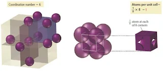
- In the simple cubic unit cell, the centres of eight identical particles define the corners of a cube.
- The particles touch along the cube edges and they do not touch diagonally along the cube faces or through its centre.
- The coordination number of each particle is 6: four in its own layer, one in the layer above, and one in the layer below.
- The edge length is 2r.
Figure 4: Simple cubic crystal structure – solid state
Figure 5: Simple cubic crystal structure
Body-Centered Cubic unit cell
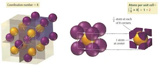
- In the body-centered cubic unit cell, identical particles lie at each corner and in the centre of the cube.
- Those at the corners do not touch each other, but they all touch the one in the centre.
- Each particle is surrounded by eight nearest neighbours, four above and four below, so the coordination number is 8.
Figure 6- Body centered cubic crystal structure – Solid State Chemistry Notes
Figure 7- Body centered cubic crystal structure
- In the body-centered cubic lattice, the atoms touch only along the cube diagonal. The edge length is 4r/√3
Face-Centered Cubic Unit Cell
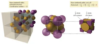
- In the face-centered cubic unit cell, identical particles lie at each corner and in the centre of each face but not in the centre of the cube.
- Particles at the corners touch those in the faces but not each other.
- The coordination number is 12.
Figure 8 – Face centered cubic crystal structure – Solid State Chemistry Notes
Figure 9- Face centered cubic crystal structure
- In the face-centered cubic lattice, the atoms touch along a face diagonal. The edge length is √8r = 2√2r (i.e. square root of 8r = two times of square root of 2r).
| Unit cell | Atoms per cell | Coordination Number | Lattice Constant | Packing Fraction |
| Simple Cubic | 1 | 6 | 2r | 52% |
| Body-Centered Cubic | 2 | 8 | 4r/√3 | 68% |
| Face-Centered Cubic | 4 | 12 | 2√2r | 74% |
Contents of a Unit Cell
- An important feature of the unit cell is the number of lattice points it contains. Atoms/ions/molecules are often located at lattice points.
- For particles of the same size, the higher the coordination number is, the greater the number of particles in a given volume.
- Since one unit cell touches another, with no gaps, a particle at a corner or face is shared by adjacent cells.
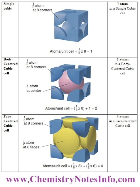
- In the cubic unit cells, the particle at each corner is part of eight adjacent cells, so one-eighth of each particle belongs to each cell. There are eight corners in a cube, so
- A simple cubic unit cell contains 8 x (1/8) particle= 1 particle
- A body-centered cubic unit cell contains 8 atoms x (1/8) particle= 1 particle + 1 particle in the centre, for a total of 2 particles.
- A face-centered cubic unit cell contains 8 x (1/8) particle= 1 particle + one-half particle in each of the six faces, 6 x (1/2) particle) = 3 particles, for a total of 4 particles.
| Atoms | Shared Between | Each atom counts |
| Corner | 8 cells | 1/8 |
| Face center | 2 cells | ½ |
| Body center | 1 cell | 1 |
| Edge center | 4 cells | ¼ |
Atomic Packing in Crystals
Square packing arrangement
- Simple cubic structure can be viewed as one layer of atoms arranged in a square pattern with the next layer stacking directly over the first.
- That is the atoms in one layer line up exactly on top of the atoms in the layer beneath it.
Figure 10: Square packing arrangement
- This type of crystal structure has a large amount of empty space
- Only 52% of the volume is occupied by the spheres, and the coordination number is 6.
Close packing arrangement
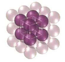
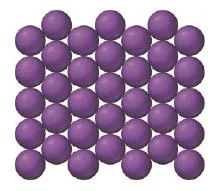
- More space-efficient packing can be achieved by aligning neighbouring rows of atoms in a pattern with one row offset from the next by one-half a sphere.
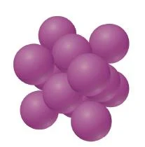
Figure 11- Close packing of spheres
- In close packing arrangement, the atoms pack more closely to each other in any one layer.
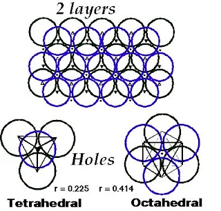
- The packing efficiency can further be increase by placing the next layer not directly on top of the first, but again offset so that any one atom actually sits in the indentation formed by three atoms in the layer beneath it, as shown below.
Figure 12- Close packing of spheres forming two layers
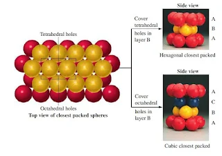
- This kind of packing leads to two different crystal structures called closest-packed structure, both of which have a packing efficiency of 74% and a coordination number of 12.
- The two closest-packed structure are-
- Hexagonal close packing
- Cubic close packing
Figure 13- Close Packing of Spheres
Hexagonal close packing
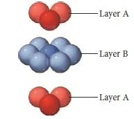
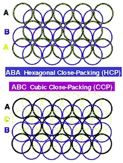
- In Hexagonal closest packing, the third layer of atoms aligns exactly on top of the first, as shown here-
Figure 14- Hexagonal closest packing
- The pattern from one layer to the next is ABAB, with the third layer aligning exactly above the first.
- The central atom in layer B of this structure is touching six atoms in its own layer, three atoms in the layer above it, and three atoms in the layer below, for a coordination number of 12.
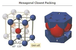
- The unit cell for this crystal structure is not a cubic unit cell, but a hexagonal one, as shown in Figure below.
Figure 15- Hexagonal closest packing crystal structure
Cubic close packing
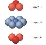
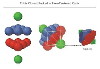
- In cubic closest packing, the third layer of atoms is offset from the first, as shown below.
Figure 16- Cubic closest packing
- The pattern from one layer to the next is ABCABC, with every fourth layer aligning with the first.
- The unit cell for cubic closest packing is the face-centered cubic unit cell, as shown in Figure.
- The cubic closest-packed structure is identical to the face-centered cubic unit cell structure.
Figure 17- Cubic closest packing
Four Ways of Packing Identical Spheres in Cubic System (Summary)
| Unit cell | Atoms per unit cell | Coordination Number | Volume occupied, % | Examples |
| Simple Cubic | 1 | 6 | 52% | Po |
| Body-Centered Cubic (bcc) | 2 | 8 | 68% | Fe, Na |
| Face-Centered Cubic (fcc) | 4 | 12 | 74% | Ag, Cu |
| Hexagonal closest packed (hcp) | 4 | 12 | 74% | Cd, Mg |
Close-packing of spheres (Summary)
|
1
|
|
|
|
2
|
|
|
|
3
|
|
|
|
4
|
|
|
Interstitial Sites (Types of holes)
- There are three types of holes present in closest packed structures-
- Trigonal holes are formed by two face-centered spheres and one corner sphere.
Figure 18- Trigonal hole – Solid State Notes
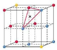
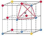
- Tetrahedral holes are formed by three face-centered spheres and one corner sphere.
Figure 19- Tetrahedral hole – Solid State Notes
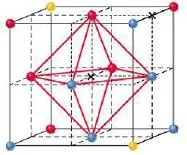
- Octahedral holes are formed by all six face-centered spheres in the cube.
Figure 20- Octahedral hole – Solid State Notes
- For spheres of a given diameter, the holes increase in size as follows-
Trigonal < tetrahedral < octahedral
- Trigonal holes are very small therefore they are never occupied in binary ionic compounds.
- The tetrahedral holes and octahedral holes in a binary ionic solid are occupied depends mostly on the relative sizes of the anion and cation.
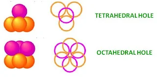
In close packing spheres, two different types of holes occur-
- Tetrahedral holes – bound by four spheres with centres at the corners of a tetrahedron
- Octahedral holes –bound by six spheres, three in one layer and three in the other. The centres of the spheres lie at the corners of an octahedron.
Figure 21- Tetrahedral and Octahedral holes in close packing structure – Solid State
- For every sphere in the close-packed arrangement there will be one octahedral hole and two tetrahedral holes.
- The octahedral holes are bigger than the tetrahedral holes.
- The radius of a sphere that will just fit into an octahedral hole in a close-packed array of spheres of radius r is 0.414 R.
Figure 22- Tetrahedral and Octahedral holes – Solid State Chemistry Notes
- For a tetrahedral hole, the radius r is 0.225 R.
- When a third layer is built up, two possibilities exist, depending on which cavities are used in the 2nd layer of spheres to accommodate the spheres of layer 3.
- 3rd layer spheres placed such that each sphere of layer 3 is directly above one in layer 1 yielding a hexagonal close-packed structure.
hcp- ABABAB
Figure 23- Structure of Hexagonal and cubic close packing – Solid State Chemistry Notes
- There is a displacement relative to 1st layer, leading to cubic close packing. Also called face-centred cubic (fcc) arrangement. 3rd layer spheres are neither above spheres in layer 1 nor layer 2.
ccp– ABCABCABC
- Close packing represents the most efficient use of space when packing equal spheres.
- In any close-packed arrangement, each atom has twelve nearest neighbours, 6 around in the same layer, 3 above and 3 below the layer.
Octahedral hole
- An octahedral site is surrounded at equal distances by six nearest-neighbour atoms.
- An octahedral sites lie at the midpoints of the edges of the face centered cubic cell unit cell.
- A cell has twelve edges, each of which is shared by four unit cells, so the edges contribute three octahedral interstitial sites per cell.
- In addition, the site at the centre of the unit cell is also octahedral, so the total number of octahedral sites per face centered cubic cell unit cell is four, the same as the number of atoms in the unit cell.
Figure 24- Octahedral hole – solid state pdf
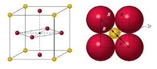
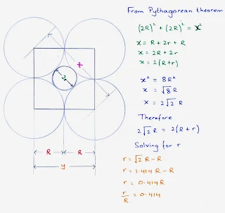
- The size of the holes is related to the radius, R, of the anions used to form the structure.
- Figure shows a cross section through an octahedral hole.
- The radius of the cation, r, which can just fit into the hole, can be found by using the Pythagorean formula, as follows.
Figure 25- Calculation for to determine the size of octahedral hole – solid state pdf
Tetrahedral hole
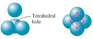
- A tetrahedral hole lies at the center of four spheres whose centers form a tetrahedron.
Figure 26- Tetrahedral hole – solid state pdf
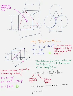
- In a face centered cubic cell, a tetrahedral site occurs in the volume between a corner atom and the three face-centered atoms nearest to it.
- In a closest packed structure, a tetrahedral site has a radius that is 0.225 times the radius of the packed spheres
- The face centered cubic cell unit cell contains eight tetrahedral sites, twice the number of atoms in the cell.
Figure 27- Calculation for to determine the size of tetrahedral hole – Solid Notes
- Interstitial sites are important when a crystal contains atoms of several kinds with considerably different radii.
Guidelines for Filling Octahedral and Tetrahedral Holes
Size of holes in a face-centered cubic unit cell
Trigonal holes = r = 0.155 R
Tetrahedral holes = r = 0.225 R
Octahedral holes = r = 0.414 R
- In the cubic closest packed structure, the octahedral hole is bigger than the tetrahedral hole.
Size of holes in a simple cubic structure
Cubic holes —-> r = 0.0732 R
- The simple cubic arrangement is not a closest packed structure and has larger holes than the cubic closest packed arrangement.
- The simple cubic structure has a cubic hole at the center of the unit cell.
- The size of the cubic hole is r = 0.732 R; of the cubic unit cells considered here, this is the largest hole.
- The cation occupies a hole that maximizes the attractions between the cation and anion and minimizes the repulsions between the anions.
- This can be accomplished by accommodating cations into holes that are slightly smaller than the actual size of the ion.
- This pushes the anions of the closest packed array slightly apart, reducing repulsions, while the anion and cation are in contact, maximizing attractions.
- Therefore, if a cation is to occupy a tetrahedral hole, the ion should be bigger than the tetrahedral hole but smaller than the octahedral hole; that is,
0.225 Ranion < rcation < 0.414 Ranion
or in terms of the radius ratio of the cation (r) to the anion (R)
0.225 < (rcation/Ranion) < 0.414
Similarly, if a cation is to occupy an octahedral hole, the radii will be governed by the radius ratio inequality
0.414 < (rcation/Ranion) < 0.732
where the upper limit of the inequality corresponds to the hole in a simple cubic lattice. When the cation is too large, that is, bigger than 0.732 R, the anions adopt a simple cubic structure, which allows the cation to be accommodated in the cubic hole of the lattice.
Guidelines for Filling Octahedral and Tetrahedral Holes (summary)
| 0.225 < (rcation/Ranion) < 0.414 | tetrahedral hole of fcc array of anions occupied by the cation |
| 0.414 < (rcation/Ranion) < 0.732 | octahedral hole of fcc array of anions occupied by the cation |
| 0.732 < (rcation/Ranion) | cubic hole of simple cubic array of anions occupied by the cation |
Types and Properties of Crystalline Solids
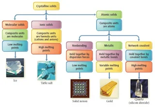
There are five different types of solids-
- Atomic Solids
- Molecular Solids
- Ionic Solids
- Metallic Solids
- Network Covalent Solids
The five types of solids are defined by the types of particles in the crystal.
Figure 28- Types of crystalline solids Notes – solid state chemistry lecture notes pdf
Characteristics of the Major Types of Crystalline Solids
| Type | Particles | Interparticle Forces | Physical Properties | Examples |
| Atomic | Atoms | Dispersion | SoftVery low melting pointPoor thermal conductorsPoor electrical conductors | Noble gases |
| Molecular | Molecules | Dispersion Dipole-dipole H-bonds | Fairly softLow melting pointPoor thermal conductorsPoor electrical conductors | Non-polar O2 Cl2 Polar SO2 H2O |
| Ionic | Positive and negative ions | Ion-ion attraction | Hard and brittleHigh melting pointGood thermal and electrical conductors when molten | NaCl CaF2 MgO |
| Metallic | Atoms | Metallic bond | Soft to hardLow to high melting pointGood thermal and electrical conductorsMalleable and ductile | Na Zn Fe |
Atomic Solids
- In an atomic solid the individual atoms held together only by dispersion forces.
- Noble gases are the only substances that form such solids.
- The very weak forces among the atoms show that melting and boiling points and heats of vaporization and fusion are all very low and it increases slightly with increasing molar mass.
- For example, Argon crystallizes in a cubic closest packed structure, as do the other noble gases.
Figure 29- Cubic closest packed structure of noble gases – Ionic Solids
Molecular Solids
- In molecular solids, the individual molecules occupy the lattice points.
- In molecular solids, there different combinations of dipole-dipole, dispersion, and H-bonding forces
- These different interparticle forces account for a wide range of physical properties.
- Dispersion forces in nonpolar substances lead to melting points that generally increase with molar mass.
- For polar molecules, dipole-dipole forces and H-bonding occurs.
- Most molecular solids have much higher melting points than atomic solids (noble gases) but much lower melting points than other types of solids.
Ionic Solids
- In ionic solids there are the interparticle forces which are called ionic bonds.
- Ionic bonds are much stronger than the van der Waals forces in atomic or molecular solids.
- To maximize attractions, cations are surrounded by anions and vice versa.
- The smaller of the two ions lies in the spaces (holes) formed by the packing of the larger ion.
- The unit cell is the smallest portion of the crystal that maintains the overall spatial arrangement; it is also the smallest portion that maintains the overall chemical composition.
- The unit cell has the same cation and anion ratio as the empirical formula.
- Ionic compounds adopt several different crystal structures, but many use cubic closest packing.
- The properties of ionic solids are related to the fixed ion positions and very strong interionic forces, which create high lattice energy.
- Ionic solids have high melting points and low electrical conductivities.
- When the ionic solid is heated and the ions gain enough kinetic energy to break free of their positions, the solid melts and the mobile ions conduct electricity.
- Ionic compounds are hard because only a strong external force can change the relative positions of the interacting ions.
- The forces holding ionic solids together are strong coulombic forces (or ionic bonds), and these forces are much stronger than the intermolecular forces, ionic solids tend to have much higher melting points than molecular solids.
- For example, sodium chloride melts at 801 °C, while carbon disulfide (CS2) which is a molecular solid with a higher molar mass and melts at -110 °C.
Cesium chloride (CsCl)
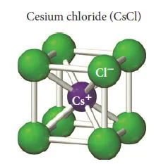
Figure 30- Cesium chloride unit cell – Ionic Solids
- Cesium chloride (CsCl) is an ionic compound with cations and anions of similar size.
- The atomic radius of Cs+ is 167 pm and the atomic radius for Cl– is 181 pm.
- In the cesium chloride structure, the chloride ions occupy the lattice sites of a simple cubic cell.
- The cesium ion lies in the centre of the cell.
- The coordination number for cesium chloride is 8, meaning that each cesium ion is in direct contact with eight chloride ions (and vice versa).
- The cesium chloride unit cell contains one chloride anion (8 x 1/8 = 1) and one cesium cation for a ratio of Cs to Cl of 1-1, as the formula for the compound indicates.
- Calcium sulfide (CaS) has the same structure as cesium chloride.
Sodium Chloride (NaCl)
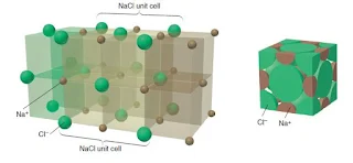
Figure 31- Sodium chloride unit cell – solid state chemistry pdf
- Sodium Chloride (NaCl) is an ionic compound with cations and anions of different size.
- The crystal structure of sodium chloride must accommodate the more disproportionate sizes of Na+ and Cl– .
- The atomic radius of Na+ is 97 pm and the atomic radius for Cl– is 181 pm.
- If ion size were the only consideration, the larger chloride anion could theoretically fit many of the smaller sodium cations around it, but charge neutrality requires that each sodium cation be surrounded by an equal number of chloride anions. Therefore, the coordination number is limited by the number of chloride anions that can fit around the relatively small sodium cation.
- The structure has a coordination number of 6 that each chloride anion is surrounded by six sodium cations and vice versa.
- Sodium Chloride is also called the rock salt structure, as chloride anions occupying the lattice sites of a face-centered cubic structure with the smaller sodium cations occupying the holes between the anions.
- The structure can also be visualise as the sodium cations occupying the lattice sites of a face-centered cubic structure with the larger chloride anions occupying the spaces between the cations.
- Each unit cell contains four chloride anions [(8 x 1/8) + (6 x 1/2) = 4] and four sodium cations [(12 x ¼) + 1= 4], resulting in a ratio of 1-1, as the formula of the compound specifies.
- Other compounds exhibiting the sodium chloride structure include LiF, KCl, KBr, AgCl, MgO, and CaO.
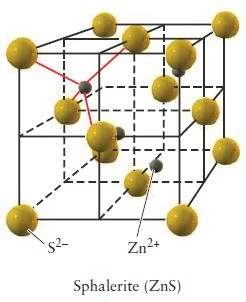
Zinc Blende (ZnS)
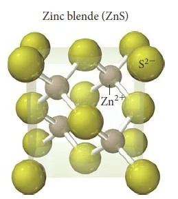
Figure 32- Zinc blende unit cell – solid state chemistry pdf
- In zinc blende there is a greater disproportion between the sizes of the cations and anions in a compound make a coordination number of even 6 physically impossible.
- The atomic radius of Zn2+ is 74 pm and the atomic radius for S2- is 184 pm.
- Zinc blende has a coordination number of 4.
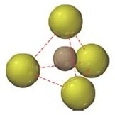
- In zinc blende, the sulfide anions occupying the lattice sites of a face-centered cubic structure with the smaller zinc cations occupying four of the eight tetrahedral holes located directly beneath each corner atom.
- A tetrahedral hole is the empty space that lies in the center of a tetrahedral arrangement of four atoms, as shown below.
Figure 33- Tetrahedral hole – solid state chapter
- Each unit cell contains four sulfide anions [(8 x 1/8) + (6 x 1/2) = 4] and four zinc cations (each of the four zinc cations is completely contained within the unit cell), resulting in a ratio of 1-1, just as the formula of the compound indicates.
Figure 34- Zinc blende unit cell (sphalerite) – solid state chemistry notes
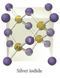
- Other compounds exhibiting the zinc blende structure include CuCl, AgI, and CdS.
Figure 35- Silver iodide unit cell – solid state chemistry notes
Calcium Fluoride (CaF2)
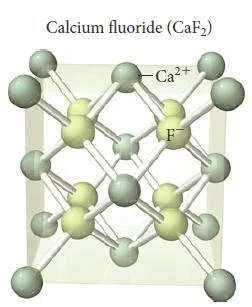
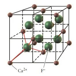
Figure 36- Calcium fluoride unit cell – Solid State Notes
- When the ratio of cations to anions is not 1-1, the crystal structure must accommodate the unequal number of cations and anions.
- Compounds that contain a cation to anion ratio of 1-2 adopt the fluorite (CaF2) structure shown in (Figure 36).
- The calcium cations occupy the lattice sites of a face-centered cubic structure with the larger fluoride anions occupying all eight of the tetrahedral holes located directly beneath each corner atom.
- Each unit cell contains four calcium cations [(8 x 1/8) + (6 x 1/2) = 4] and eight fluoride anions (each of the eight fluoride anions is completely contained within the unit cell), resulting in a cation to anion ratio of 1-2, just as in the formula of the compound.
Figure 37- Calcium fluoride unit cell – Solid State Notes
- Other compounds exhibiting the fluorite structure include PbF2, SrF2, and BaCl2.
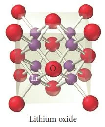
Figure 38- Lithium oxide unit cell – Solid State Notes
Figure 39- Barium chloride unit cell – Solid State Notes
Antifluorite Structure
Compounds with a cation to anion ratio of 2-1 often exhibit the antifluorite structure, in which the anions occupy the lattice sites of a face-centered cubic structure and the cations occupy the tetrahedral holes beneath each corner atom.
Metallic Solids
- Metallic elements form closest packed structures.
- In contrast to the weak dispersion forces in atomic solids, powerful metallic bonding forces hold atoms together in metallic solids.
- The properties of metals are-
- High electrical conductivity
- High thermal conductivity
- Malleability- result from their delocalized electrons
- Melting points and hardnesses of metallic solids are also related to packing efficiency and number of valence electrons.
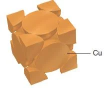
Copper adopts cubic closest packing
Figure 40- Copper unit cell – Solid State Notes
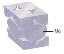
Figure 41- Magnesium unit cell (magnesium adopts hexagonal closest packing) – Solid State Notes
Figure 42- Unit cell of Polonium, Manganese and Silver – solid state chemistry notes
Network Covalent Solids
- Strong covalent bonds link the atoms together in a network covalent solid.
- Covalent Solids adopt variety of crystal structures depending on the details of their bonding.
- As a result of the strong covalent bonds, all network covalent solids have extremely high melting and boiling points, but their conductivity and hardness vary.
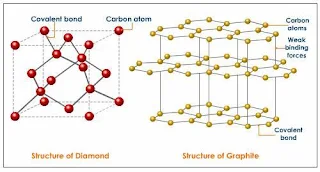
- For examples, graphite and diamond have the same element which is carbon atoms, but have different properties.
Graphite
- Graphite occurs as stacked flat sheets of hexagonal carbon rings with a strong σ-bond framework and delocalized π-bonds, the arrangement looks like a honeycomb.
- The π-bonding electrons of graphite are delocalized over the entire sheet.
- Graphite is good conducts of electricity. It is commonly used as electrode material.
- The sheets interact via dispersion forces, and impurities, such as O2, between the sheets allow them to slide past each other, which explains why graphite is soft and used as a lubricant.
Figure 43- structure of Diamond and Graphite – solid state chemistry notes
Diamond
- Diamond adopts a face-centered cubic unit cell, with each carbon atom tetrahedrally bonded to four others in an endless array.
- Diamond contains strong single bonds which make it the hardest natural substance known.
- Diamond does not conduct electricity because the bonding electrons are localized.
Join us at Social Media
Hope you enjoy learning B.Sc. Chemistry Notes on Solid State Chemistry. You can also explore these interesting science topics-
- Definition Symbol Formula SI Unit and Measurement of Density
- Formula & Relationship Between Degree Celsius, Degree Fahrenheit and Kelvin
- Forensic Science - Famous Forensic Scientists and Forensic Chemist
- Chemical Arithmetic and Chemical Stoichiometry
- What are Essential Amino Acids
- Peptide Synthesis
- Catalytic Decomposition of H2O2 – Elephant’s Toothpaste Experiment
- What is Organic Chemistry ?


